Beschreibung
Discontinued, replaced by LVR500 Series.
Click here if you want to know more about level measurement.
The LVR20/30 Series has been discontinued as it not CE Compliant. Please see the LVR500 Series as a possible alternative or contact our Technical Sales department.
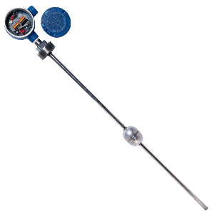
The OMEGA ® LVR20 and LVR30 Series continuous liquid level sensors operate on a basic voltage divider network principle. As the float rises, a magnet in the float closes a series of reed switches in sequence which varies the tapped-off portion of the voltage divider resistor network. The LVR20 has the basic voltage divider output—the regulated DC voltage input equals the maximum voltage output. The LVR20 has a nominal 1,200 resistance; thus, with a 10 Vdc supply, 8.3 mA of current are required. The OMEGA ® DPF52 or DP24-E panel meters can be used to power and display the resistance from the LVR20; when relays are required, the DP25E-A meter can be used. For maximum accuracy, the readout device for the LVR20 should be zero and span adjusted after wiring is completed to compensate for any effects due to the resistance of the lead wires. The LVR20 can also be made intrinsically safe when used with OMEGA’s intrinsic safety barriers and when properly powered. The LVR30 Series is provided with a signal conditioner to provide a 4-20 mA output when powered by 10-30 Vdc. The LVR30 Series cannot be made intrinsically safe. All LVR30 units are supplied with a J-box with screw terminal connections. All LVR20 units are supplied without a J-box with 24 inches of bare wire coming out of the top of the unit with a 1 /2 " MNPT conduit connection. All LVR20 and LVR30 Series units can be wired for increasing output with either increasing or decreasing height of liquid; standard output is increasing output with increasing height. For other lengths, adaptor systems are available. They consist of two parts: the LVR-C coupling (2 x 2" FNPT) and an LVR-A pipe nipple (2 x 2" MNPT) of various lengths to change the insertion depth of the LVR20 or LVR30 sensor. When using the adaptors, a zero offset is introduced into the output signal which must be compensated for in the readout device (for example, the mA signal will not go down to 4 mA, nor will the voltage output go down to zero). Retaining clip pliers are required to remove the float when using the adaptor system.
Please download PDF below for complete product specifications
 SCHLIESSEN


