Torque Measurement
Torque Applications
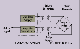
Sensor Configurations A strain gage can be installed directly on a shaft. Because the shaft is rotating, the torque sensor can be connected to its power source and signal conditioning electronics via a slip ring. The strain gage also can be connected via a transformer, eliminating the need for high maintenance slip rings. The excitation voltage for the strain gage is inductively coupled, and the strain gage output is converted to a modulated pulse frequency (Figure 6-5). Maximum speed of such an arrangement is 15,000 rpm.

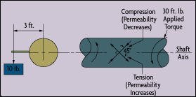
Figure 6-4: Torque on a Rotating Shaft
Torque is measured by either sensing the actual shaft deflection caused by a twisting force, or by detecting the effects of this deflection. The surface of a shaft under torque will experience compression and tension, as shown in Figure 6-4. To measure torque, strain gage elements usually are mounted in pairs on the shaft, one gauge measuring the increase in length (in the direction in which the surface is under tension), the other measuring the decrease in length in the other direction.
Early torque sensors consisted of mechanical structures fitted with strain gages. Their high cost and low reliability kept them from gaining general industrial acceptance. Modern technology, however, has lowered the cost of making torque measurements, while quality controls on production have increased the need for accurate torque measurement.
Applications for torque sensors include determining the amount of power an engine, motor, turbine, or other rotating device generates or consumes. In the industrial world, ISO 9000 and other quality control specifications are now requiring companies to measure torque during manufacturing, especially when fasteners are applied. Sensors make the required torque measurements automatically on screw and assembly machines, and can be added to hand tools. In both cases, the collected data can be accumulated on dataloggers for quality control and reporting purposes.
Other industrial applications of torque sensors include measuring metal removal rates in machine tools; the calibration of torque tools and sensors; measuring peel forces, friction, and bottle cap torque; testing springs; and making biodynamic measurements.
Torque can be measured by rotating strain gages as well as by stationary proximity, magnetostrictive, and magnetoelastic sensors. All are temperature sensitive. Rotary sensors must be mounted on the shaft, which may not always be possible because of space limitations.

Figure 6-5: Inductive Coupling of Torque Sensors
Strain gages also can be mounted on stationary support members or on the housing itself. These "reaction" sensors measure the torque that is transferred by the shaft to the restraining elements. The resultant reading is not completely accurate, as it disregards the inertia of the motor.
Strain gages used for torque measurements include foil, diffused semiconductor, and thin film types. These can be attached directly to the shaft by soldering or adhesives. If the centrifugal forces are not large--and an out-of-balance load can be tolerated--the associated electronics, including battery, amplifier, and radio frequency transmitter all can be strapped to the shaft.
Proximity and displacement sensors also can detect torque by measuring the angular displacement between a shaft's two ends. By fixing two identical toothed wheels to the shaft at some distance apart, the angular displacement caused by the torque can be measured. Proximity sensors or photocells located at each toothed wheel produce output voltages whose phase difference increases as the torque twists the shaft.
Another approach is to aim a single photocell through both sets of toothed wheels. As torque rises and causes one wheel to overlap the other, the amount of light reaching the photocell is reduced. Displacements caused by torque can also be detected by other optical, inductive, capacitive, and potentiometric sensors. For example, a capacitance-type torque sensor can measure the change in capacitance that occurs when torque causes the gap between two capacitance plates to vary.
The ability of a shaft material to concentrate magnetic flux--magnetic permeability--also varies with torque and can be measured using a magnetostrictive sensor. When the shaft has no loading, its permeability is uniform. Under torsion, permeability and the number of flux lines increase in proportion to torque. This type of sensor can be mounted to the side of the shaft using two primary and two secondary windings. Alternatively, it can be arranged with many primary and secondary windings on a ring around the shaft.
A magnetoelastic torque sensor detects changes in permeability by measuring changes in its own magnetic field. One magnetoelastic sensor is constructed as a thin ring of steel tightly coupled to a stainless steel shaft. This assembly acts as a permanent magnet whose magnetic field is proportional to the torque applied to the shaft. The shaft is connected between a drive motor and the driven device, such as a screw machine. A magnetometer converts the generated magnetic field into an electrical output signal that is proportional to the torque being applied.
| References & Further Reading | |
| Omegadyne Pressure, Force, Load, Torque Databook, Omegadyne, Inc., 1996. | |
| The Pressure, Strain, and Force Handbook, Omega Press LLC, 1996. | |
| Industrial Control Handbook, E. A. Parr, Butterworth, 1995. | |
| Instrument Engineers' Handbook, Bela Liptak, CRC Press LLC, 1995. | |
| Instrumentation Reference Book, 2nd Edition, B.E. Noltingk, Butterworth-Heinemann, 1995. | |
| "Overcoming the High Cost of Torque Sensing in Industrial Applications," Darrell Williams, Eaton Corp., 1998. | |
| Process/Industrial Instruments and Controls Handbook, 4th Edition, Douglas M. Considine, McGraw-Hill, 1993. | |
| Sensor and Analyzer Handbook, H.N. Norton, Prentice Hall, 1982. | |
| "Sensors: The Next Wave of Infotech Innovation," Paul Saffo, Institute for the Future,1998. | |
| Van Nostrand's Scientific Encyclopedia, Douglas M. Considine and Glenn D. Considine, Van Nostrand, 1997. | |
| Vibration Analysis for Electronic Equipment, 2nd Edition, Dave S. Steinberg, Wiley, 1988. |