Protective Accessories
The most obvious gauge accessory is a shutoff valve between it and the process (Figure 5-2), which allows blocking while removing or performing maintenance. A second valve is often added for one of two reasons: draining of condensate in vapor service (such as steam), or, for higher accuracy applications, to allow calibration against an external pressure source.
Other accessories include pipe coils or siphons (Figure 5-2A), which in steam service protect the gauge from temperature damage, and snubbers or pulsation dampeners (Figure 5-2B), which can both absorb pressure shocks and average out pressure fluctuations. If freeze protection is needed, the gauge should be heated by steam or electric tracing.
Chemical seals (Figure 5-2C) protect the gauge from plugging up in viscous or slurry service, and prevent corrosive, noxious or poisonous process materials from reaching the sensor. They also keep the process fluid from freezing or gelling in a dead-ended sensor cavity. The seal protects the gauge by placing a diaphragm between the process and the gauge. The cavity between the gauge and the diaphragm is filled with a stable, low thermal expansion, low viscosity and non-corrosive fluid. For high temperature applications, a sodium-potassium eutectic often is used; at ambient temperatures, a mixture of glycerine and water; and at low temperatures, ethyl alcohol, toluene, or silicon oil.
The pressure gauge can be located for better operator visibility if the chemical seal is connected to the gauge by a capillary tube. To maintain accuracy, capillary tubes should not be exposed to excessive temperatures and should not exceed 25 feet (7.5 m) in length. The chemical seal itself can be of four designs: off line, "flow-through" type self-cleaning, extended seal elements, or wafer elements that fit between flanges.
The spring rate of the diaphragm in the chemical seal can cause measurement errors when detecting low pressures (under 50 psig, 350 kPa) and in vacuum service (because gas bubbles dissolved in the filling fluid might come out of solution). For these reasons, pressure repeaters often are preferred to seals in such service. Pressure repeaters are available with 0.1% to 1% of span accuracy and with absolute pressure ranges from 0-5 mm Hg to 0-50 psia (0-0.7 to 0-350 kPa).
 |
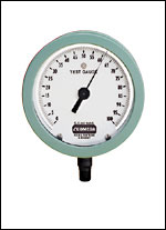
| Pressure guages come in a wide variety of ranges and units. |
Pressure Switches
Pressure switches serve to energize or de-energize electrical circuits as a function of whether the process pressure is normal or abnormal. The electric contacts can be configured as single pole double throw (SPDT), in which case the switch is provided with one normally closed (NC) and one normally open (NO) contact. Alternately, the switch can be configured as double pole double throw (DPDT), in which case two SPDT switches are furnished, each of which can operate a separate electric circuit. The switch housings can meet any of the NEMA standards from Type 1 (general purpose) to Type 7 (explosion proof), or Type 12 (oil tight).
 |
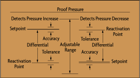
| Figure 5-3: Pressure Switch Terminology |
Figure 5-3 illustrates the terminology used to describe pressure switch functionality and performance. When the pressure reaches the setpoint (which is adjustable within the range), the switch signals an "abnormal condition" and it does not return to "normal" (the reactivation point) until the pressure moves away from the abnormal condition by the "differential" (also called dead-band). The precision of setpoint actuation is called its "accuracy," while the precision of reactivation is called "tolerance."
| References & Further Reading | |
| Omegadyne Pressure, Force, Load, Torque Databook, Omegadyne, Inc., 1996 | |
| The Pressure, Strain, and Force Handbook, Omega Press LLC, 1996. | |
| Instrument Engineers' Handbook, Bela Liptak, CRC Press LLC, 1995. | |
| Process/Industrial Instruments and Controls Handbook, 4th Edition, Douglas M. Considine, McGraw-Hill, 1993. |